
In this post from Lighting Series, we are going to talk about light and radiometry. We will not enter in full detail about radiometric units in this post. In the next post, we are going to talk about radiant energy and radiant power (radiometric units).
What is light?
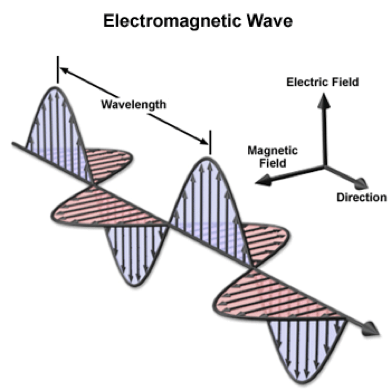
Light is a form of electromagnetic radiation, a sinusoidal wave formed by coupled electric and magnetic fields. These fields are perpendicular to each other and to the direction of propagation. The wavelength of a sinusoidal wave is the spatial period of the wave. The frequency of the oscillation determines the wavelength.
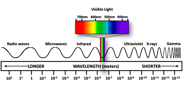
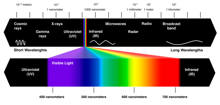
Electromagnetic radiation can exist at any wavelength. There are radio waves, microwaves, infrared, light, ultraviolet, x-rays, and gamma rays.
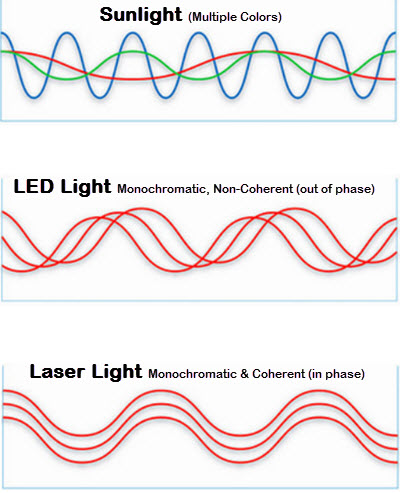
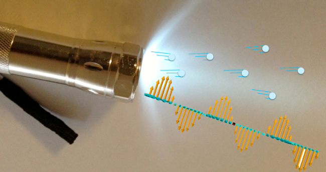
A pure source of light (laser) consists of light at a single frequency. Laser light is coherent, that is, the source is tuned so that the wave stays in phase as it propagates. In the natural world, light almost always exists as a mixture of different wavelengths, and it is incoherent.
Example of coherent and incoherent lights:
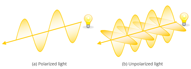
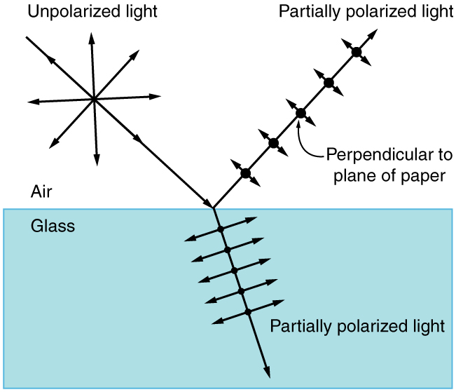
Electromagnetic radiation can be polarized, that refers to the preferential orientation of the electric and magnetic field vectors relative to the direction of propagation. Unpolarized light consists of many waves that are summed with random orientation. This is typically ignored in computer graphics.
Example of polarized and unpolarized lights:
Example of polarization-unpolarization when light interacts with a surface:
Optics theory and algorithms can be applied to light because it is a form of electromagnetic radiation. The study of optics can be divided into three subareas: geometrical or ray optics, physical or wave optics, and quantum or photon optics.
Quantum optics can explain the behavior of light at the submicroscopic level (for example, photons or particles). This model is too detailed and not commonly used in computer graphics.
Physical or Wave optics is described by Maxwell’s equations and captures effects like diffraction, interference, and polarization that arise when light interacts with objects of size comparable to the wavelength of light. For the purposes of image generation, it is typically ignored.
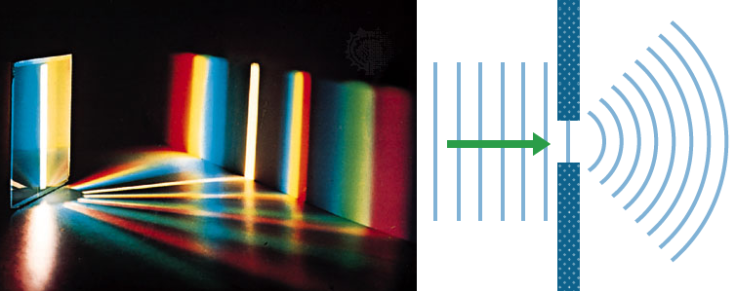
Diffraction refers to various phenomena that occur when a wave encounters an obstacle or a slit.
Example of diffraction:
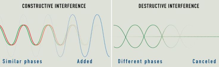
Interference is a phenomenon in which two waves superpose to form a resultant wave of greater, lower, or the same amplitude.
Example of interference:
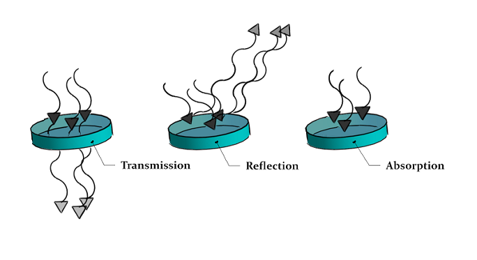
Geometric optics focuses on calculating macroscopic properties of light as it propagates through environments. It also assumes that light is emitted, absorbed, reflected, and transmitted, and that the wavelength of light is much smaller than the scale of the objects that the light interacts with.
The following assumptions can be made in this model:
- Visible light (or thereabouts)
- Incoherent light
- Unpolarized light (random polarization)
- Macroscopic scale
- Light travels in straight lines (diffraction is not considered)
- Light travels instantaneously through a medium (infinite speed).
- Light is not influenced by external factors (gravity or magnetic fields)
Example of absorption, reflection, and transmission:
What is radiometry?
Radiometry is the science of measuring radiation energy in any portion of the electromagnetic spectrum. In practice, the term is limited to the measurement of ultraviolet (UV), visible (VIS), and infrared (IR) radiation.
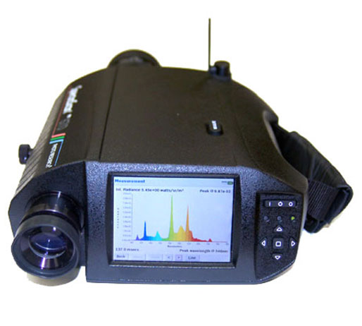
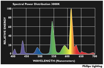
The amount of light at each wavelength can be measured with a spectroradiometer, and its resulting plot of measurements is the spectrum of the source.
Example of spectroradiometer:
Radiometry was originally built on an abstraction of light based on particles flowing through space. Using the mental model of photons as particles works well for the most part. As we mentioned, some physical phenomena cannot be modeled without accounting for the wave properties of photons (polarization, interference, diffraction, etc). These properties can be ignored in real-time rendering.
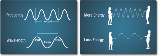
The wave-related property about that each photon has an associated frequency or wavelength is not ignored. The energy of each photon is proportional to its frequency, and this affects interactions between photons with sensors (rods and cones in the human eye). The relationship between a photon’s wavelength λ (in meters), frequency v (in Hertz, or cycles per second), and energy Q (in joules) are:
v = c / λ
λ = c / v
Q = h * v
where c is the speed of light and h = 6.63 * 10^-34 J is the Planck’s constant.
Example of frequency, wavelength, and energy:
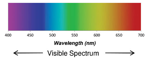
In the range of human vision, the different frequencies are perceived as light of different colors. For rendering, the human visible spectrum between 380 to 780 nanometers is used. The lower wavelengths (400 nm) are the bluish colors, the middle wavelengths (550) are the greens, and the upper wavelengths (650nm) are the reds.
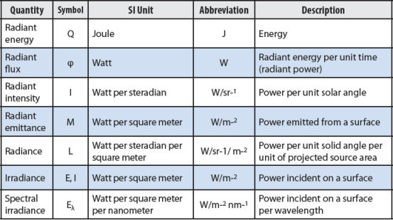
The SI System (Système International d’unites) defines six radiometric for describing the radiation coupling between a light source and an optical system. The most commonly used units are: Radiance, Irradiance, and Radiant Flux.
These radiometric quantities are each described by their spectral power distribution (SPD), that is a distribution function of wavelength that describes the amount of light at each wavelength.
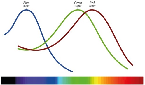
It is important to find good basis functions to represent SPDS, that map the infinite-dimensional space of possible SPD functions to a low-dimensional space of coefficients Ci in real numbers. The typical computer graphics practice is to represent SPDs with coefficients for red, green, and blue colors (refer to RGB Color Model article to know more about this). When we display an RGB color on a display, the spectrum that is displayed is determined by the weighted sum of the spectral response curves for red, green, and blue, as emitted by the display’s phosphors, LED or LCD elements, or plasma cells.
In the next post, we are going to talk about radiant energy and radiant power (radiometric units.)
References
Real-Time Rendering, 3rd Edition
Physically Based Rendering, 3rd Edition: From theory to implementation
Fundamentals of Computer Graphics, 4th Edition
Essential Mathematics for Games and Interactive Applications, 3rd Edition
Introduction to Computer Graphics: A Practical Learning Approach, 1st Edition
