
In this opportunity, we are going to talk about perspective projection matrix computation.
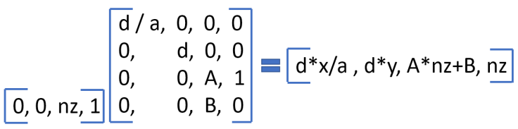
Remember in Part 1 that for View Space we defined a camera in DirectX with the following properties:
- Camera is at (0.0, 0.0, 0.0, 1.0)
- Forward vector is +z = (0.0, 0.0, 1.0, 0.0)
- Up vector is +y = (0.0, 1.0, 0.0, 0.0)
- Side vector is +x = (1.0, 0.0, 0.0, 0.0)
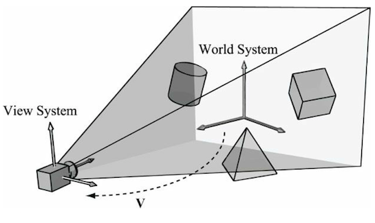
and we transformed our point Pw (in world space) using the View Space matrix.
Subsequently, we transformed our point Pv to homogeneous clip space, using a perspective projection matrix.
I am a DirectX user, so all I will describe here is related to that API. OpenGL/Vulkan is similar, but I am not going to mention/explain them.
But, why does it have the name “perspective” projection matrix and not only projection matrix?
There are several types of projection:
- Perspective projection
We are going to describe only perspective projection (check hyperlinks for the others). It is important in computer graphics because it models the way the human visual system works. If we stand on some railroad tracks and look down a straight section, the rails will converge in the distance, and the ties will appear to shrink in size and become closer together.

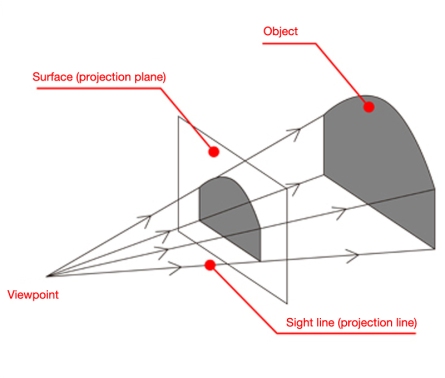
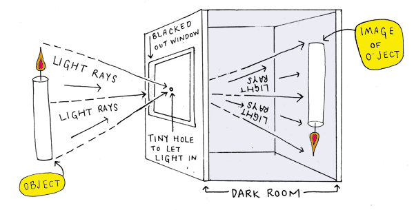
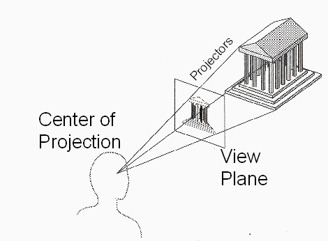
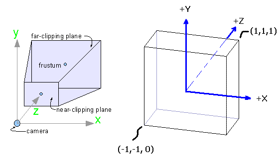
The goal here is to project the point Pv onto a plane, called the projection plane. To understand how this works, we will examine an old form of projection known as the camera obscura.
The camera obscura is a darkened room with a small hole allowing a fraction of light to enter the room. This light is projected onto the opposite wall of the room, displaying an image of the world outside. That image will be upside down and flipped left to right.
Remarks:
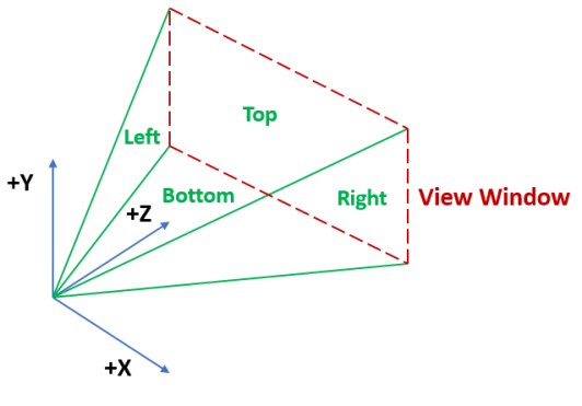
- All the lines of projection pass through a single center of projection (the tiny hole in the above picture)
- The virtual film is a rectangle on the view plane, known as the view window (where the image of the object is in the above picture)
- As an object moves farther away, its corresponding projection will shrink on the projection plane.
- Lines that are parallel in view space will appear to converge as their extreme points move farther away from the eyepoint.
Ok, we understood why we choose perspective projection, but the image in the view window is upside down and flipped left to right, and we do not see the real world in that way.
The projection plane must be moved to the other side of the center of projection, which is known as the as our view position.
Now, how do we project a 3D point onto our new projection plane?
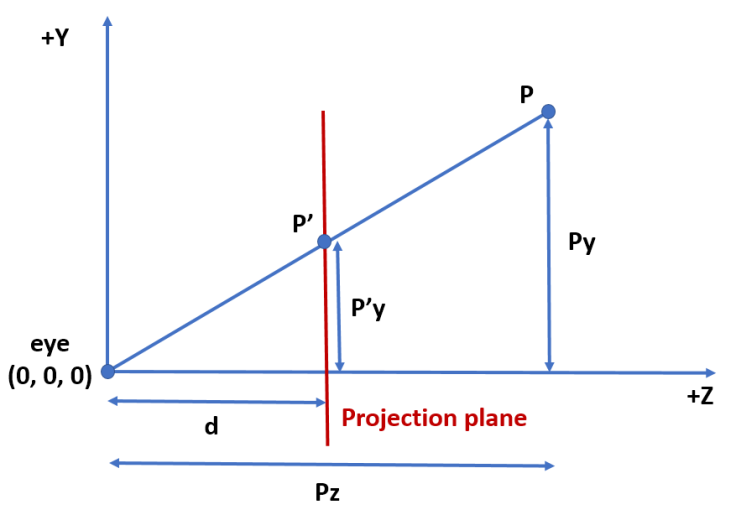
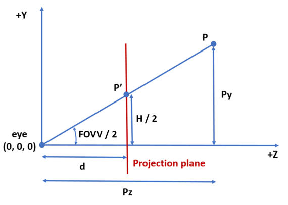
To simplify this problem, we will use a 2D view of the yz plane, as shown in the following image.
Explanation:
- P is the 3D point we want to project onto the projection plane.
- P’ is the projected point we want to find in the projection plane.
- d is the distance from the eye to the projection plane.
- The eye is at (0.0, 0.0, 0.0) (given camera properties definition)
By similar triangles property,
P’y / d = Py / Pz
then P’y = d * Py / Pz
Similarly,
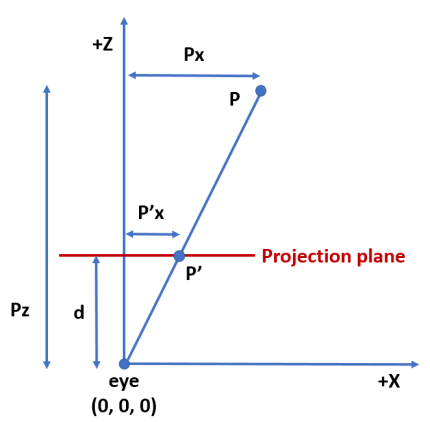
P’x = d * Px / Pz
As we are projecting a 3D point onto a plane, the resulting z coordinate (P’z) will always be the same: P’z = d
Finally, the point in the projection plane is P’ = (d * Px / Pz, d * Py / Pz, d)
Apparently, we cannot build a matrix for this transformation because as we have Pz division in P’x and P’y, this transformation is not affine nor linear. To be able to do that, we need to represent point P’ in homogeneous space coordinates
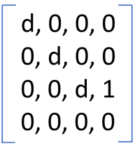
P’ = (d * Px, d * Py, d * Pz, Pz)
and this is a 4D linear transformation, where our basis vectors are
(d, 0, 0, 0)
(0, d, 0, 0)
(0, 0, d, 1)
(0, 0, 0, 0)
Then our homogeneous perspective projection matrix is
Interesting “points”:
- If Pz is d, then P’ = (d * Px, d * Py, d * d, d). After perspective divide, we get P’ = (Px, Py, d, 1.0). The points in the projection plane are not moved.
- If Pz is 0.0, then P’ = (d * Px, d * Py, 0.0, 0.0). This means that eyepoint moves to infinity.
- If Pw is 0.0 and Pz != 0.0, then P’ = (d * Px, d * Py, d * Pz, Pz). After perspective division we get P’ = (d * Px / Pz, d * Py / Pz, d, 1.0). This means that a point infinitely far forward becomes a local point.
Ok, with the perspective projection matrix we end projecting all the world in the projection plane. It is infinite (by definition) and of course bigger than the view window that ends on our monitor screen. How do we determine what will lie within our view window?
We could project all objects to the projection plane and convert them to pixels. After that, we can ignore pixels outside the view window. The problem with this approach is that for complex scenes with a lot of objects, it is inefficient.
To constrain what we render in the view window xy directions, we define 4 planes aligned with the edges of the view window. Each plane is specified by the eyepoint and two adjacent vertices of the view window.
The angle between the upper plane and the lower plane is called the vertical field of view (FOVV). The angle between the left plane and the right plane is called the horizontal field of view (FOVH)
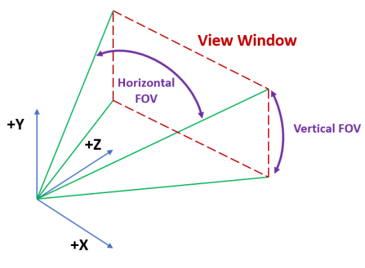
Commonly, only one of them is used because the other can be calculated using the former. We choose the vertical field of view.
The vertical field of view, the view window size and the projection plane distance (d, in our equations) are related. Given 2 of them, we can compute the third.
If the view window size is fixed, then if the field of view gets larger, d needs to get smaller to maintain the view window size. Similarly, a small field of view will lead to a longer d.
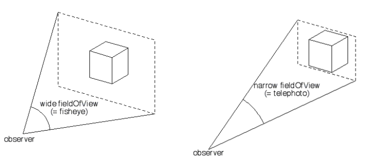
If d is fixed, then the larger the field of view, the larger the view window size (making more objects visible in our scene).
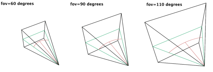
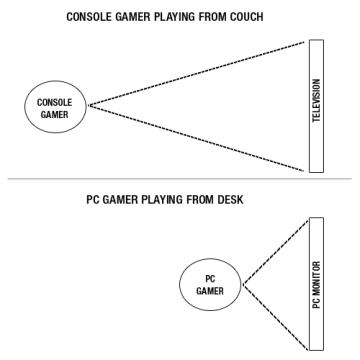
The vertical field of view chosen needs to match the display medium. For a standard widescreen monitor placed about 1 meter (~3ft), the monitor only covers about a 40-45 degree vertical field of view from the perspective of the user. However, the usual compromise is to set the vertical field of view to the range of 60-90 degrees, because the distortion is not that perceptible and it allows the user to see more of the world. (Section 7.3.3 of Essential Mathematics for Games and Interactive Applications – 3rd Edition)
Ok, suppose we know the view window size (for example, W and H) and the vertical field of view (for example, FOVV). Then how can we compute d to replace it in our current perspective projection matrix?
To do this calculation, we use the perspective projection of a point that is projected onto the upper plane (remember the four planes aligned with the edges of the view window) (we could use the bottom plane too). We can see that situation in the following diagram.
P’y will be H / 2 because view window height is H and it goes from -H / 2 to H / 2.
Then, using trigonometry
(H / 2) / d = tan(FOVV/ 2)
then d = (H / 2) / tan(FOVV / 2)
then d = (H / 2) * cot(FOVV / 2)
Ok, with the perspective projection matrix we end projecting all the world in a plane, and part of it will end in our monitor, but our monitor screen resolution is not square. Does the perspective projection matrix we built work for this case too?
If our view window is square, then we could use the same P’y formula for P’x, because the field of view does not matter, as the vertical and horizontal field of view angles are the same. Most view windows are rectangular to match the relative dimensions of the chosen display (computer monitor, tablet, cellphone, etc.). In this case, the aspect ratio (W / H) will be different than 1.0.
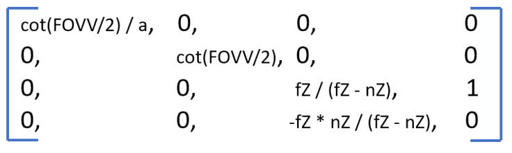
In particular, we decide to use a view window where H = 2 so d computation can be reduced to the following:
d = (H / 2) * cot(FOVV / 2) = cot(FOVV / 2)
and the matrix will be
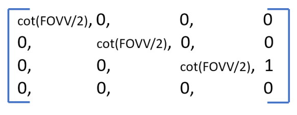
NDC y coordinate will belong to [-1.0, 1.0]
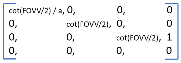
As aspect ratio a is W / H, then W = a * H = 2 * a. Then you can see that NDC x coordinate will belong to [-a, a], but as we saw in Part 1, NDC x must belong to [-1.0, 1.0]. That range must be accomplished because otherwise, we would need to tell the hardware the aspect ratio since the hardware will later need to do some operations that involve the dimensions of the view window.
Then we need to remove this dependency on the aspect ratio in the following way:
a * P’x / cot(FOVV / 2) = Px / Pz
then P’x = cot(FOVV / 2) * Px / (a * Pz) = (cot(FOVV / 2) * Px / a) / Pz
then P’ = (cot(FOVV / 2) * Px / a, cot(FOVV / 2) * Py, cot(FOVV / 2) * Pz, Pz)
and the updated perspective projection matrix will look like this
What happens if a point is in the eye? There will be a division by zero. And what happens to points behind the projection plane? They will be projected upside down and flipped left to right.
These are important problems to address. As we mentioned, projected eyepoint moves to infinity, i.e. Wp = 0.0. We cannot do perspective divide for obvious reasons. We also should clip points behind the projection plane. To accomplish this, we define a plane that constrains objects in the projection plane z direction: the near plane.
We can also optionally define a far plane, which also constrains objects in the projection plane z direction. It is useful for culling objects beyond it (we will see in the next post about the depth buffer that near and far planes can be inverted to get interesting results)
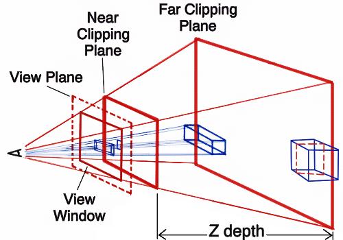
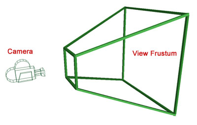
With these six planes (the four planes aligned with the edges of the view window + near plane + far plane) we have a closed view frustum or view volume.
Anything inside these planes will be rendered; everything outside them will be ignored.
In DirectX the Z coordinate in NDC space ranges from 0.0 to 1.0, while it ranges from -1.0 to 1.0 in OpenGL. So NDC space is cubic in OpenGL but it is not in DirectX. You can see in the following picture, the transformation from View Space to NDC Space (perspective projection transformation + NDC transformation) in DirectX.
Why in the picture above, Zndc is mapped to [0.0, 1.0]? After all, the projection plane is at a fixed distance from the eye.
Conceptually, losing a dimension makes sense because we are projecting from a 3D space down to a 2D plane, but many rendering algorithms use the post projection z values to do depth comparisons and other stuff (for example, post-processing effects like SSAO).
We need to map [nZ, fZ] to [0.0, 1.0]. There are 2 parts:
- Scale the interval to a width of 2
- Translate it to [0.0, 1.0]
We can get the result by creating a perspective matrix with unknowns for the scaling and translation factors:
After perspective divide we get
Zndc = A + B / nZ
We know that a point with z = nZ maps to 0.0, then
B = -A * nZ
Similarly,
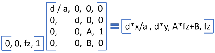
After perspective divide we get
Zndc = A + B / fZ
We know that a point with z = fZ maps to 1.0, then
1.0 = A + B / fZ
By B substitution
1.0 = A – A * nZ / fZ
then 1.0 – A = -A * nZ / fZ
then fZ – A * fZ + A * nZ = 0.0
then fZ + A * (nZ – fZ) = 0.0
then A = fZ / (fZ – nZ)
By A substitution in B = -A * nZ equation
B = (-fZ / (fZ – nZ)) * nZ
then B = -fZ * nZ / (fZ – nZ)
After all these calculations, our final perspective projection matrix is the following:
The obvious mapping for [nZ, fZ] is [0.0, 1.0] as Hodgman mentioned in a GameDev’s post:
“Also, it’s standard practice these days to map the far-plane to 0.0 and the near-plane to 1.0…”
We are going to talk about that in the next post about how perspective projection and depth buffer are related.
DirectXMath library has a method to compute the perspective projection matrix we developed. It is XMMatrixPerspectiveFovLH.
References
In addition to all the links cited in the article, I used the following references:
Section 4.4 – Mathematics for 3D Game Programming and Computer Graphics
Chapter 7 – Essential Mathematics for Games and Interactive Applications
Section 6.4 – 3D Math Primer for Graphics and Game Development
Chapter 18 – A Trip Down the Graphics Pipeline – Jim Blinn
Section 5.6 – Introduction to 3D Game Programming With DirectX 12
In the next post, I am going to write about how perspective projection and depth buffer are related.
